The End of an Unsuccessful
Project
I cannot find any air leaks
now and yet the engine is not self sustaining. The force delivered by the
piston seems to be too small to turn the flywheel. I think I have come as far
as I can with this design and it’s time to call the Terrapin project dead.
This is video of me hand-cranking the engine.
Parts of this project
worked quite well:
- A cheap and airtight piston can be made with a
bike inner-tube and a bucket.
- The phase angle between the power piston and
regenerator can be easily adjusted on the fly by using two concentric
axles pinned together by a pointer on the flywheel face.
- A very good regenerator can be made by
alternating aluminum screens with nylon netting. The temperature of the
lower cold chamber did not appreciably increase over the nominal 22C even
thought the top chamber was over 100C, while the engine was being cranked.
- An adjustable and calibrated electrical heat
source can be made from a thrift store toaster and a wall dimmer.
- The power piston stroke length was adjustable
on the fly by moving a control rod.
Parts of the project I had
trouble with:
- The strength and insulation properties of wood
are superb but it is very difficult to make an airtight wooden box.
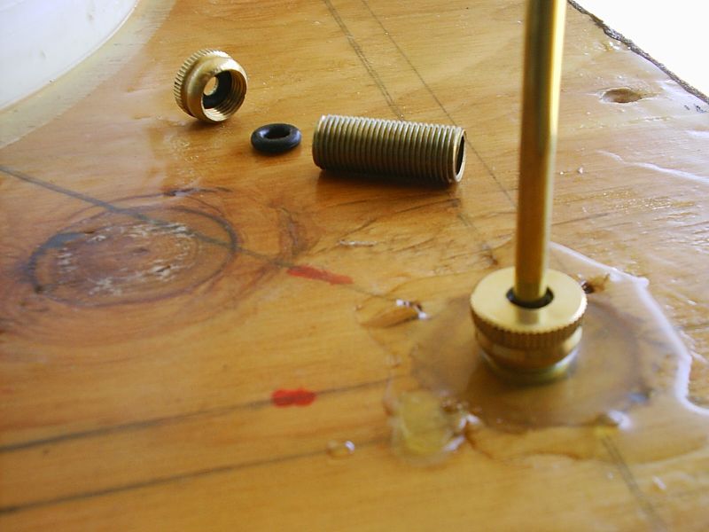
- The regenerator rod O-ring seals, that I made,
needed to be adjusted very tightly to become airtight. This caused
friction during the regenerator rod travel.
- The engine produced very little power with the
80C temperature gradient. The size of the regenerator vessel must need to
be very large to produce usable power at such temperatures.
- The project was over-budget. The parts that make up the engine cost about $175.
Closing Remarks
Stirling Engines still intrigue me and I may very well
attempt to build another. Here, I learned of several new techniques that I can
apply to future projects. For low temperature-gradient engines, the
displacement vessel must be quite large to develop appreciable power. Building
large airtight insulated vessels that can withstand alternating positive and
negative pressures is challenging.