Friday, October 26, 2012


Casting About For Engine Dimensions                                                            


I found several web pages about designing Stirling engines that were quite helpful. Zig's HomePage on Stirling Engines at http://mac6.ma.psu.edu/stirling/has many valuable and quite technical links. Doug Conner at http://www.solarheatengines.com/shares good experimental data, showing that the high to low temperature ratio must be of slightly higher value than the ratio between the largest and smallest engine volumes. Indeed, if the power stroke is larger than the changes in volume due to temperature, then the engine is not going to run. Also if the power stroke is too short then little power is produced. For a given engine and temperature difference there is an optimum power stroke. The power stroke is very sensitive to changes in temperature.

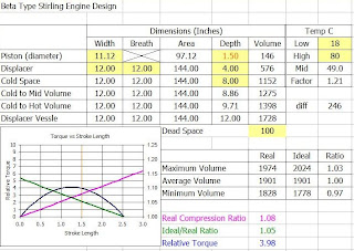
If I am understanding this right, I made an excel sheet that theoretically models the relative power produced by different engine designs. I reckoned that the torque produced by the engine (power?) is the pressure force on the piston, times the crank arm radius. The force on the piston would be proportional to the difference  in volumes between the total real physical engine space and the ideal total engine volume that the gas wants to expand into, if it were not bound. The ratio between these volumes needs to be above one, if the piston is to move outwards and less than one if the piston is to move inwards. The crank arm radius is proportional to the size of the power stroke. Want a bigger stroke; make a wider crank.

Another assumption I made was that the average of the so-called ideal engine volume exactly matches the average of the true physical volume of the engine. The pressure inside a running engine bounces positively and negatively about normal room pressure. There must be small venting of the vessel to the outside or the piston would blow out as the engine warmed up and the air expands. Some of the ideal volume has leaked away from a hot engine. So I calculate the maximum ideal volume by adding half the ideal increase to the real average volume and the minimum ideal volume by subtracting half the increase from the real average volume. The difference of the min and max ratios of the ideal to real volumes, plus one, is as close as I come to a number representing engine stroke force.

I multiply the above ideal-to-real volume ratio by the depth of the stoke and the area of the piston head to get a torque value that is in arbitrary units. Plots of length of stroke vs. torque, form smooth rising then falling arcs. Maximum torque should be the stroke length at the top of the arc. Interestingly, the point of maximum torque is when the engine’s real compression ratio equals the ratio between the ideal volume and the real volume. I am assuming this would be for an engine with no load or friction. I am expecting a real loaded engine would use somewhat smaller power strokes to produce optimum power than the graph predicts .

If you want to play with the Power Design excel sheet, then you can download it at the following link. All but the highlighted cells are protected from entries but you can unprotect the sheet in the Excel Tools menu if you want to tinker around with the formulas.

Sunday, October 21, 2012


Rethinking the Engine ...  Plan B                                                          


I am starting to get a better understanding of the materials I will need to build an engine. What I have come to realize, is that a type A engine needs a very large amount of gas volume in each of it’s pistons. The power produced by the engine comes from the difference of the volumes of the hot and cold pistons. For a 100°C temperature difference, for each unit of cold volume there is 372/272 or 1.37 units of hot volume. The combined piston maximum volumes would be 2.37 units and the difference of the hot and cold volumes is 0.37 units. That means that only 0.37/2.37 or 15.6% of the piston movements are converted into power. In a type B engine, all of the piston’s power stroke  movement is attempted to be harnessed for power. It's the same amount of work; just using a smaller piston. The upshot is I can make a much bigger B type engine by using the same piston I was planing to make for the A type engine.


The reason I wanted to build a Type A engine in the first place, was to utilize the pistons to pump gas through heat exchangers on the way out of the regenerator. I reckoned that the regenerator would need to be stationary to do so. I think there is a better way.

 I have a new design for a four beam type B engine that will meet my design concepts, is mechanically simpler than the type A and produces more power per volume of the, now, single piston. The model will be build around an 11 inch diameter piston made from a paint bucket and will have an adjustable stroke of up to 1.5 inches (145 cubic inches). The gas inside the piston will be at the hot working temperature and will flow into the piston through a stationary heat exchanger. There will be a small pump at the bottom of the regenerator/displacer vessel, operated by the displacer movement, that pumps air though the cold heat exchanger.


Friday, October 19, 2012


Thinking about Regenerators                                                                                                              


Imagine a regenerator that has room for gas of volume V, in and around the wirey solid  material that it contains. Let’s say the regenerator (and the gas it initially contains) is at a temperature half way between the hot and cold temperatures of the engine. Now, very slowly, push in cold gas from one end. The gas is coming in so slowly that it comes to temperature equilibrium with the surrounding solid phase as it moves along. Push the cold gas in, such that the entire volume V is displaced by new gas. This takes less than volume V of cold gas because the cold gas expands as it warms up. The leading edge of the cold gas warms up to the solid phase temperature quite quickly because it is always encountering new warm solid phase. After the gas is at solid phase temperatures, it no longer cools the regenerator solid phase. The net effect is that the cold temperature front lags behind the new gas front, by quite a bit. In fact, because the heat capacity of a volume of the solid phase is about a hundred times that of the same volume of the gas phase, very little of the regenerator material is cooled down. A temperature curve along the cold gas filled regenerator at equilibrium might look like the solid blue line in the graphic.


In an ideal world, if you played the above scenario in reverse, then all the air coming back out of the regenerator would be cold and would contract to its original size and the regenerator would revert to a midpoint temperature.

If hot air is slowly pumped in from the hot side then the equilibrium temperature curve would look like the solid red line. A larger volume of hot gas needs to be pumped because it contracts inside the regenerator. The volume of cold or hot gas that undergoes expansion or contraction during a cycle is represented by the light red and blue shaded areas on the graph. It is important to note, that during each single hot or cold part of the cycle, that both the hot and cold working volumes are undergoing contraction or expansion. As the hot cycle part of the gas exits the regenerator it expands and, at the same time, the cold cycle part of the gas enters the regenerator and also expands. So the total volume of gas expanding or contracting during each half cycle can be represented by adding the blue and red areas on the graph. The white areas of the graph are volumes where work is not being done.


A longer, thus narrower regenerator (V is being held constant), causes higher gas velocities and causes more resistance to gas flow. Higher gas velocities could cause the gas to move though the regenerator without a chance to come to equilibrium with the surrounding solid phase, or perhaps faster moving air removes (and adds?) heat faster from the solid phase. I think ether of these effects would  widen the ideal sharp temperature gradient shoulder on the graph. 

Also, it is possible to saturate the first part of the regenerator solid phase to the temperature of the incoming gas. The more gas that enters the regenerator per square unit of it’s face (long and narrow regenerator), the more likely that part of the regenerator will go to saturation. None of the gas in the part of the regenerator at saturation undergoes contraction (or expansion) and robs pressure from the power stroke.


A regenerator with a wide face and with very shallow depth would have an extremely sharp temperature gradient from one side to the other. Heat does not like to stay where you put it; it diffuses away. Regenerators can be built with stacked wire screens that run perpendicular to the gas flow, to try and keep heat in the same lateral plane. But if the regenerator is too shallow the temperature gradient could be muddied and heat exchange inefficient. 

I conclude that the amount of regenerator solid phase is not critically important as long as it is in large excess of the gas’s heat capacity. 
A target volume  for the gas phase part of the regenerator is simply the cold piston volume adjusted to the mid- temperature in degrees Kelvin or 
VRgas = Vcold x Kmid / Kcold. 
The volume (cM3) of the solid phase part of the regenerator is its weight divided by its density, or for steel  
VRsolid = Grams of solid phase ÷ 7.8 G/CM3
The total regenerator volume is the sum of the solid and the gas volumes. 
The optimum shape for a regenerator is probably slightly wider across the face than along the axis of gas flow. I’m hoping the shape is not critical over a wide range of values.

Sunday, October 14, 2012


A Ten Beam Engine                                                                                                  


Now I know why the SunPulse folks went with a Beta type engine. The timing and volume of single power stroke is much easier to adjust and the controls make intuitive sense.


To make an alpha engine act  similarly to a beta engine, the vessel containing the displacer moves and the displacer remains stationary. Think of both pistons moving together as one, surrounding a stationary displacer. Here, the displacer is the regenerator with the heat exchangers inside. I want to do it this way so the pistons can pump air though the heat exchangers, hopefully improving power.


The ten beam engine design uses an adjustable chain and four sprockets to change crank phase angles. Changing a piston volume is done with a cantilevered lever system. The changes these controls make in the piston volumes and timing are now independent of each other, so adjustments on the fly should make intuitive sense. 

I have a space in the garage corner that is 5 x 3 feet where my table saw now sits. I am thinking a full size engine should have a 4’ x 3’ footprint. The pistons each would be 24” in diameter with about 2.5 inches of travel giving a volume of 1130 cubic inches . A half scale model would be 24” x 14” with 141 cubic inches per piston. The quarter scale 18 cubic inch piston is probably too weak to get an engine to turn. There is an eight foot space behind the garage where  a monster 5.2 cubic foot engine could sit. My neighbors would probably call the cops on me.

Friday, October 12, 2012


Stirling Engine Designs                                                                        


I want to build an alpha type Stirling engine where the stationary regenerator sits between two opposing pistons. The pistons could be connected to cranks with two beams (gray).


It is possible that a two beam engine, with cranks of the same size, set at 90 degrees phase, could be the best of all possible configurations. What a coincidence it would be, if this simplest engine was the best. I cannot help thinking that the engine’s power would be optimized if there was an adjustment for timing as the engine ran at different speeds; as is the case of a car engine. 


Adjustments to the timing and volumes can be achieved with as few as four beams


The combined volumes of both pistons follow a sinusoidal curve of changing volume over time that is close to, but not exactly, a sin wave.


By playing with an excel simulator, it looks as though all volume curves are possible by tweaking the crank diameter and the phase difference between the two cranks.


 However, I see that if the phase angle between the cranks is changed, then both the timing and the amplitude of the piston volumes change unpredictably. The same is true if I change a crank diameter, both the amplitude and the timing of the piston volumes change. This is going to make it difficult to design an engine that I can make intuitive changes on the fly.

I’m currently working on a ten beam plan that is mechanically complex. I am concerned about the inertial mass of all the moving parts and about vibration from the many joints rattling. 

Tuesday, October 9, 2012


Stirling Engines                                                                                                                                                                       


Stirling engines are mechanically simple but complex in design. I have known about their existence for a long time but had not really “gotten it” until after some additional reading this week. In a Beta Stirling engine, a gas is cyclically heated and cooled by moving the gas in and out of regions containing solids that are already hot or cold. This movement of gas takes little energy because it is accomplished with a light-weight displacer in a closed vessel. The displacer does not compress the gas and except for some gas rushing around in there, no work is done. Warming gas expands and cooling gas contracts. The energy of the changing pressure in the closed vessel is captured by a piston and, when the piston moves, is referred to as the power stroke. The work done by the power stroke is transferred to a flywheel,  which in turn powers the displacer. Because gas is difficult to heat and to cool rapidly, most of the heat transfer happens in a regenerator which is filled with a high surface area material like steel wool. The regenerator temporarily stores the heat (or lack of heat) of the alternating cycles and improves the efficiency of the engine. 


In an Alpha Stirling engine, there is no displacer. The gas is pushed back and forth through the regenerator by two  pistons. The power stroke force comes from the increase in combined volumes from both pistons.

Wikipedia has some great animations of Stirling engines.

Stirling engines that use air as the working gas are said to be inefficient in extracting work from the heat energy supplied. These weak engines have more power if the heat difference is higher. The spa is 20C when cold and 40C when hot. I am thinking of circulating vegetable oil in a parabolic solar array for attaining input temperatures of greater than 100C. The engine’s low extraction of the heat from the solar array fluid may actually help keep the input temperature nice and high.


I am very impressed with the SunPulse engine (beta type I think) in the Youtube video (prior post). Their solar fed engine produces 1.5 KWatts of electricity. I am thinking of an alpha type engine about half that size to power two cheap sump pumps. I have some ideas on how to improve the efficiency of the alpha engine. 


My Working Concepts for Building a Stirling Engine.


1. Use a stationary regenerator with two identical but opposing pistons to move the gas back and forth through the regenerator; an alpha type engine. 

2. Heat exchangers are incorporated into the regenerator so that the air exiting to a piston is heated (or cooled) as it passes. Air coming into the regenerator takes a different path.

3. Use rolled cloth piston seals for a completely closed system. It could be possible to use helium as the fluid gas.

4. Power stroke (sum of both piston volumes) is variable. May change from zero to high compression ratios during engine operation.

5. Phase angle between pistons is changeable during engine operation. 

6. Pragmatically, find optimal engine parameters by studying the effects of temperature, flow-rate, phase angle, compression and running speed on an operating engine.

7. Make  a ¼ or ½ scale model of the engine to study efficiency and power. Because power is proportional to the volume of the working gas, doubling the size of an engine should increase the power produced by a factor of eight and quadrupling by a factor of 64. There is no need to make an engine that requires more heat energy than the solar collectors can produce.

8. Use scrounged, recycled or hardware-store-off-the-shelf materials. Use simple bench-top tools for fabrication. Budgeting $100 for the first model. That does not include anything solar at this time.

Possible New Projects Including a Stirling Engine                                                 


I calculated that running the spa on average 1/2 hour per day, only costs $52 a year for power and gas. For a spa solar heater I would need: two 12 volt 6 amp pumps ($100), 144 watts of solar panels ($200). a heat exchanger ($70), check valve ($20), solar heat collectors ($60), pipe, fittings, insulation and wire ($100). and a ($50) budget buffer. That’s at least $500 for the project. At $52 a year savings it takes about ten years to pay back the investment. It is a cool project but it is hard to justify the money and time spent.

The doghouse (computer, frig and power bricks) uses a little less than 200 watts per hour. 24 hours x 365 days = 1728 KWatts/year. We pay on average $0.182 per KW,  so the doghouse costs about $315 a year to operate. To get back the 200 watts a day with just eight hours of sunshine, I need 600 watts of panels ($840) and probably four big acid/lead batteries ($400). After 3 years the batteries need to be replaced. Maybe $2000 altogether or payback in about six years. 

I have huge trees that overshadow my house on the south side, so solar collectors on the roof are not gong to work. My wife is not comfortable with the aesthetics of solar arrays in the backyard. The garage roof is probably the best place for a solar array but it is about 80 feet from the doghouse. I need to percolate this idea some more...

While researching solar collectors, I ran across George Plhak’s excellent blog on parabolic collectors and also the Tamera SolarVillage Youtube video about using a large Stirling engine to pump water.


I am intrigued by the idea that the temperature difference between solar array fluid and spa water could be used to circulate both fluidic systems. A Stirling engine is essentially a heat exchanger that extracts mechanical work in the process. So, could I build a large cheap Stirling engine and use it in place of the heat exchanger, the electric motors and the photovoltaic panels of the spa solar heating project?