Saturday, October 5, 2013

Jackrabbit Finished                                                                             

Finished engine.
While the house windows are on order, I completed the building of the Jackrabbit engine. The pistons and vessels are completely air tight. 


Air cooler.
The water cooling coil in the second engine worked so well (25ºC maintained) , I put an air cooler in the first engine also. 


Controller and relays.
I mounted the Arduino  micro-controller and the relay boards in a box. I have a well working Arduino program that runs the engine. 


Pressure in vessel A (black), pressure
in B (blue), RPM (red), relays(magenta)
A host computer graphical interface allows me to tweak the engine timing in real time and record engine telemetry. The fans move the air from cold to hot spaces in about a second without causing stray electrical interference now. The heaters maintain 85ºC with about 120 watts of power. 


Unfortunately, the engine is still not self sustaining. I tried many timing schemes but the flywheel eventually comes to a stop. The amount of  friction in the system does not seem to be excessive, so I believe the problem lies with the small amount of  torque that the engine produces. Even if I did manage to get this engine to be self sustaining, I don’t think it could generate enough electricity to power the fans.

My original question was, “Can a Stirling engine extract  usable work from a low temperature gradient?” The answer is, probably no. I could not do it with the small gradient of  60ºC ( cool air of 25ºC and warm air of 85ºC). In my mind, this question has been laid to rest and I can now finally move on to where my muse leads me next.

Thursday, August 22, 2013

Noise Filter                                                                                                                                                       

Motor noise filter.
I added three ceramic capacitors across the hair dryer motor and the USB motor noise interference is gone. The following link was very helpful:


I heated the engine up to 80ºC and the engine is not quite self sustaining. I can tell that I am close. One problem is that the cold side of the engine warms about 10ºC for every five minutes of use. By the time the hot side has warmed to 80ºC, the cold side is at 35ºC. Without active cooling I can only get, at maximum, a 45ºC temperature gradient for a few minutes. The engine was designed to run on a 60ºC temperature difference and that 15ºC is sorely missed. Power of these engines seems to increase exponentially as the temperature gradient increases.The whole challenge of this experiment was to see if usable work could be extracted from a low temperature gradient. I must start thinking about installing water cooled tubing.

I am going ahead with the building of Jackrabbit’s second engine. The second engine’s power stroke is offset from the first engine’s by 90 degrees. The combination should supply continuous torque to the flywheel, through the entire engine cycle. I will experiment with adding a cooling coil to the second bucket. If I have success, I will retrofit the first bucket with a cooling coil.


We  are thinking of installing eight new windows in the front of the house. When I start working on that, this engine project will have to be delayed.

Saturday, August 17, 2013

Pressure Tests                                                                               


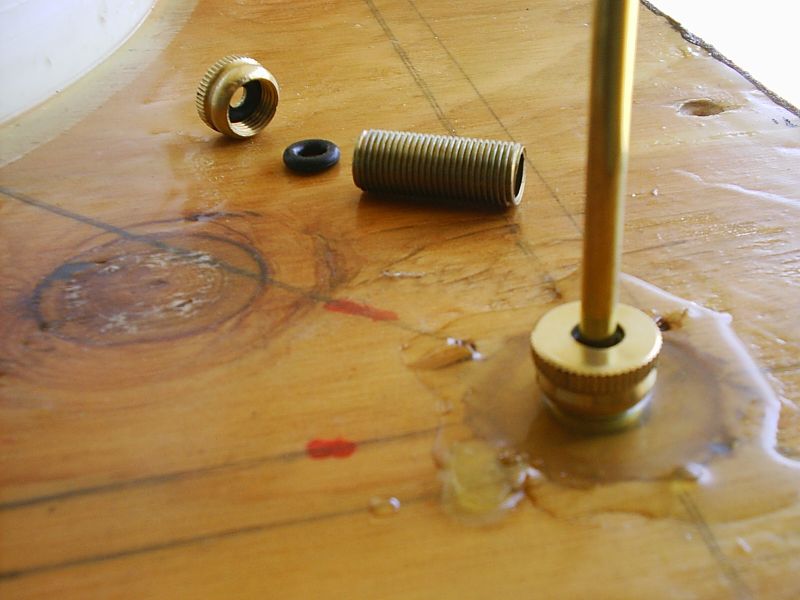
The bucket was easily made air tight by placing a 2mm bead of modeling clay on its lip before sealing the lid. The allthread clamps hold the lid on securely.


The programming and interfacing of the Arduino Uno was challenging but not impossible. I found Beginning Arduino Programming by Brian Evans to be an excellent text. An Arduino C-like program gets written and uploaded from your computer, though a GUI supplied by Arduino.  The Arduino program environment consists of a global variable definition section, a setup section that is executed only once and a loop section that runs continuously thereafter.


Arduino sketch
The Arduino program is designed so it can run the engine independent of the desktop computer, but information and control is available when it is connected to the desktop graphical interface. The Arduino program keeps track of the engine timing, reads the sensors and actuates the fan and heater relays. Each time a crank sprocket blocks the timing sensor (48 times per revolution), telemetry is sent to the desktop interface;


Telemetry example : “44 15 85 010 #”
            Crank position (0-47)  zero = TDC
            Engine speed  (milli-seconds since last crank sprocket detection)
            Engine relative air pressure (PSI times 100)
            Relay values as a binary string (fan switch 1 & 2, heater switch)  
            End of data string character (#)

 I wrote a VB6 graphical interface that receives and graphs the real-time engine telemetry and also sends single character commands to the Arduino program over the connecting USB cable.  The commands are:
            “0” for stop engine and exit test mode
            “1” for start engine
            “2” for change the baud rate to 38400
            “3” for turn on fan and heater*
            “4” for turn off fan*
            “5” for turn off heater*
            “6” enter test mode
*The fan and heater timing commands are time dependent and are sent only once,  just prior to the desired change.  The change is remembered by the Arduino program and is used during subsequent cycles.


Piston pressure real-time graph.
In RUN mode, the Arduino program uses the crank angle position to control the fan and heater relays. This real-time graph is of pressure (black), speed (red) and switch values (magenta), as I manually turn the crank with no heat supplied and the valve between the piston and bucket open (connected). The changes in pressure are due solely to the pumping of the piston. There is a pressure range of about 0.6 PSI to -0.5 PSI.


Piston pressure simulation.
 It is gratifying that the graph of the real data looks remarkably similar to the pressure (blue) predicted by my engine simulation program. The simulation gives a pressure range of positive 0.77 PSI to -0.72 PSI.


Regenerator pressure real-time graph.
In TEST mode the Arduino simulates the crank movement at a rate of one sprocket position every 15 mS.  I ran the engine in TEST mode with the heater and fan cycling on and off and the valve closed to the piston (a completely closed bucket).  The change in pressure is due solely to the action of the air moving back and forth through the regenerator. Temperatures at 60ºC and 23ºC.  Pressures at +0.6 PSI and -0.3 PSI


Regenerator pressure simulation.
It is interesting that the real-time pressure curve increases and decreases linearly as the fan moves the air through the regenerator, instead of the sinusoidal curve as predicted in the engine simulation program. Simulation pressures were at +0.8 PSI and -0.6 PSI


The engine has not produced enough power to run by itself yet. I am having some very frustrating fan motor problems that interfere with the USB cable data transmissions. I keep loosing the interface when the fan runs. I must reopen the bucket to add noise filtering capacitors to the hair dryer motor before doing more tests.

Saturday, August 3, 2013

Jackrabbit Engine                                                                                 


Jackrabbit Layout.
I am making an engine for the Jackrabbit out of a five gallon open-head HDPE bucket. I wanted to use five gallon steel pails but none are available locally and I cannot afford the online shipping fees. HDPE is pliable when over 100ºC and 82ºC is listed as the maximum safe working temperature. I am going to try to keep temperatures under 80ºC. Most of the heat is concentrated in the top ¼ of the bucket. In that part, I have doubled the wall thickness of the plastic and I have also reinforced the plastic lid  and bucket bottom with sheets of wood. 


Regenerator and fan in bucket.
Sitting ¾ of an inch below the lip of the bucket is a donut-like regenerator made from alternating layers of aluminum screen and nylon netting. Poking through the center of the regenerator is a three inch diameter metal tube containing an electric hairdryer motor and heating element.
 
Engine animation.
The polarity of the energized fan, determines the direction of the air blowing through the regenerator. Hot air blows though the center fan tube into the top of the regenerator and cold air comes out the bottom of the regenerator. In the bottom ¾ of the bucket, the hot air and the cold air volumes are kept separated by a plastic bag partition. The fan repeatedly fills and empties the bag with hot air within the surrounding space of cold air. The amount of air in the bucket is fixed, so the pressure of the air in the bucket increases and decreases each cycle. A flexible hose runs from the cold side of the bucket to the piston.


One engine simulation
I have not, as of yet, added water tubing for the heating and the cooling of the engine air, but I have left room for copper coils above and below the regenerator. For my initial tests, the electric heating element and the ambient air temperature should give me a temporary temperature gradient of about 60ºC.


Bucket clamped down.
A pressure test of the HDPE bucket fails to keep even one PSI of pressure from leaking out from under the lid within a few seconds. I am thinking that I can make the bucket airtight if I seal the lid with aquarium glue. Each PSI of over-pressure inside the bucket produces 94 pounds of upward force on the lid. I am using 3/8” allthread clamps to hold the lid tightly down on the bucket with about 150 pounds of force. During the vacuum part of the engine cycle, an additional 118 pounds of downward force is felt by the lid. I am hoping the hot HDPE bucket can withstand the stress.

Sunday, July 14, 2013

Jackrabbit On It's Way                                                                                                    

Insides of a piston.
Good news: I have pistons that work well. After several variations, I found that  the inside of PVC pipe is smoother than ABS pipe. The finished cylinders are about 16 inches long with an 11” stroke and a 4” inside diameter. The lubricated o-ring slides easily in the PVC cylinder. I can rapidly stop the flywheel from turning by putting a finger over the air inlet tube during both the compression or the vacuum phase of the stroke. I do not feel any air leaks.


Dual pistons 90 degrees out of phase.
The flywheel is also finished. I scavenged a discarded bicycle from Isla Vista after the students moved out for the summer. I mounted the cut-off back half of the bike, upside-down on a board so the crank can turn the tire freely. I removed the gear shifters, shortened the chain, welded the rear sprocket to the rear wheel (crank and wheel always move together now) and welded one of the crank pedals at a 90 degree angle (instead of the normal 180 pedal configuration). The pistons pivot on a 3/8” steel rod welded across where the seat post would have gone.


I gave up on making PVC over-pressure and under-pressure relief valves. I just could not make a ball valve that would not leak a little air. I tried plastic balls and stainless steel balls to no avail. Instead I will use small electric air valves. If the controller senses pressures that are too high or too low, then it will open a valve to vent to the outside.


Jackrabbit layout of components.
Next, I have to locate containers to make into displacer vessels. There are definitely going to be two Stirling engines connected to one flywheel. My calculations predict the finished engine should produce about five foot-pounds of torque for a 60C temperature gradient. I will be happy if the engine can just sustain the turning of the flywheel. The Jackrabbit is off to a good start.


Thursday, June 20, 2013

Rabbit                                                                                                                      

The Rabbit engine layout
The Terrapin project was so slow and bulky it would not run. I hope the single engine Rabbit project runs a little faster. I may add a second engine and call it JackrabbitLepus californicus.

Click images for bigger views.


Piston and Cylinder
The piston cylinder is made from a 12 inch piece of ABS 4” drain pipe. I picked a pipe that was fairly smooth on the inside. I glued a ½” PVC barbed fitting into the 4” cap and pushed a 5” piece of 13/32” brass tubing though holes drilled in the cap’s sides. The cylinder will pivot about this point on a 3/8’ steel axel as the connecting rod moves on the crank.


Piston Seal
The piston head is made from three Plexiglas discs (turned on a router table) and a 4” o-ring sandwiched together. The o-ring is held to the cylinder wall by the pressure (or vacuum) inside the piston and it slides well with the help of a slathering of petroleum jelly. The o-ring seal is the only moving part of the project where I have to contend with air leaks. If the finished piston leaks, then the project will be postponed until I can make a functioning piston.


SMPP-03 Calibration Graph
I ordered several pressure sensors and temperature sensors from Mouser electronics. I mounted a SMPP-03 sensor ($4.50) and a small op-amp board ($0.49) inside a PVC fitting.  At ambient pressure, the unit outputs 1.85 V. The voltage changes linearly from 0.5V to 3.75V over the entire +7 PSI range. I am working on PVC overpressure and underpressure relief valves. I have $5 worth of 5/8” rubber balls, coming from Smallparts.com.

PVC Parts


Ardunio Uno R3
I ordered an Ardunio Uno R3 micro controller on eBay for $16.49. With it, I should be able to control and monitor the engine by way of a USB cable to an old desktop XP computer. I will be attempting to write a VB6 interface program to send engine commands and collect data. I have a steep learning curve ahead, but I have wanted to learn about this supposedly excellent product for a long time, and this project is a good fit for this device. Even if the engine does not run, I will have learned something new.


Wednesday, June 5, 2013

An Engine Simulation Program                                                                         

I've been thinking about a new Stirling engine project that uses a fan to blow cold air through the regenerator into the hot space and visa-versa. The vessel would contain a plastic bag to keep the hot and cold air from mixing.


Simulation Program. Click for bigger view.
I wrote a VB6 simulation program that (I hope) models what happens when the engine runs. The program calculates the instantaneous torque produced by the engine for each degree of movement of the flywheel. For each position of the flywheel, I know the piston volume , the vessel volume, the dead space volume and the total volume of the engine in cubic inches. Also for each position of the flywheel, I know the ratio of hot and cold air in the vessel and I can calculate what that associated hot/cold air volume would be if it were unbound so as to expand (or contract) it’s volume to keep the air pressure at an ambient 15 PSI. From the ratio of the total volume and the unbound volume I calculate the pressure in the vessel that fluctuates positively and negatively about the ambient pressure each cycle. The force on the piston head is calculated, as is the torque delivered to the flywheel by the connecting rod. It turns out that a wheel driven by a connecting rod does not exactly follow a sinusoidal curve. With a bit of creative programming I think I now accurately calculate the reciprocating piston position and the true force the connecting rod imparts tangentially to the flywheel.


Pressure-Blue,     Force-Red,     Torque-Green
Because  power is transferred to the flywheel as the air is expanding and again as the air is contracting, two peaks per cycle are seen on the torque curve (green). For bigger piston volumes, the torque can momentarily become negative, although curiously, the average torque is still larger than for a smaller piston.


Torque-Green ,  2nd Torque Curve-Orange,   Sum-Purple
If two of these engines are coupled at a phase of 90 degrees, then the torque curves add to make a relatively constant positive torque value. I 
incorporated torque curve: duplication, offset, summation and scaling functions, into the program by mouse clicking on the graph. There are a lot of bells and whistles in this program and I believe it does a good job of simulating the kind of engine I have in mind to build. You may download the simulator from the following link. It is called RabbitSimulation.exe.

https://docs.google.com/file/d/0B9fsJB6CcZqrVW9fMVBEVVJTZVE/edit?usp=sharing

Sunday, June 2, 2013


A New Concept                                                                                    


The view from the doghouse today.
I’ve dismantled the Terrapin, cleared off the garage workbench and cleaned out the doghouse; time for a new project...

I must be a gluten for punishment but I’m not done with the Stirling engine bug yet. I really want to know if usable work can be extracted from a low temperature gradient, of say, 80C. I am tired of patching air leaks in wooden boxes and of complex mechanical linkages. What I want to do is to build a simple experimental engine from which I can collect experimental data. I have some concepts that I am thinking about:

  1. Keep this engine mechanically simple so that a minimum amount of energy is lost to friction.
  2. Use a calibrated electric heat source so I can track the amount of energy going into the engine.
  3. Use an off–the-shelf air tight containment vessel.
  4. Instead of using a displacer to move air between hot and cold chambers, use a fan to move air though a stationary regenerator. An air-tight vessel will use a plastic bag partition to keep the hot and cold air volumes from mixing.
  5. Experiment with making a piston from a metal can.
  6. Gearing the piston output so that the flywheel turns many times each engine cycle.
  7. Use a small generator coupled to the flywheel to measure output work.
  8. Make over-pressure and under-pressure safety relief valves.
  9. Use a computer to monitor and control the engine in real-time.
  10. Use mostly recycled or scrounged materials with a budget of $100.
  11. Write a simulation program that models what I might expect in the way of output power.
I am going to start with the simulation program and then see what develops.


Saturday, May 25, 2013

The End of an Unsuccessful Project                                                

I cannot find any air leaks now and yet the engine is not self sustaining. The force delivered by the piston seems to be too small to turn the flywheel. I think I have come as far as I can with this design and it’s time to call the Terrapin project dead.


This is video of me hand-cranking the engine.


Parts of this project worked quite well:

  1. A cheap and airtight piston can be made with a bike inner-tube and a bucket.
  2. The phase angle between the power piston and regenerator can be easily adjusted on the fly by using two concentric axles pinned together by a pointer on the flywheel face.
  3. A very good regenerator can be made by alternating aluminum screens with nylon netting. The temperature of the lower cold chamber did not appreciably increase over the nominal 22C even thought the top chamber was over 100C, while the engine was being cranked.
  4. An adjustable and calibrated electrical heat source can be made from a thrift store toaster and a wall dimmer.
  5. The power piston stroke length was adjustable on the fly by moving a control rod.

Parts of the project I had trouble with:

  1. The strength and insulation properties of wood are superb but it is very difficult to make an airtight wooden box.
  2. The regenerator rod O-ring seals, that I made, needed to be adjusted very tightly to become airtight. This caused friction during the regenerator rod travel.
  3. The engine produced very little power with the 80C temperature gradient. The size of the regenerator vessel must need to be very large to produce usable power at such temperatures.
  4. The project was over-budget. The parts that make up the engine cost about $175.

Closing Remarks


Stirling Engines still intrigue me and I may very well attempt to build another. Here, I learned of several new techniques that I can apply to future projects. For low temperature-gradient engines, the displacement vessel must be quite large to develop appreciable power. Building large airtight insulated vessels that can withstand alternating positive and negative  pressures is challenging.


Disgruntled                                                                                   


Well, I got so disgruntled with the engine that I worked on other projects for a while.

No mater how many coats of epoxy resin that I applied to the outside of the box, there were always air leaks (detected by soapy water) bubbling from multiple odd places on the sides and lid of the box. The wood is very porous to air and it lifts and splits the brittle epoxy. I have used resin reinforced by fiberglass cloth before and it is rather tedious to work with and it also leaks air if every single hole in the cloth is not completely saturated with resin. I looked around for an alternate sealing material and settled on Kevlar reinforced bed liner.

The stuff is not cheap; a quart cost me $36 !  I applied four coats of the black stuff to the sides, bottom and top lips of the box. I coated the inside of the lid as well. I now use aquarium glue and two inch screws to secure the lid.


I reworked the difficult-to-adjust regenerator rod seals to a better design using modified lamp parts. I glue one inch long, 3/8” diameter, threaded lamp tubes into the lid where the regenerator rods pass though. Then I screw on 3/8” brass lamp caps that has a hole drilled in it for the rod to pass through. An O-ring fits nicely under the cap and provides an easily adjustable air-tight seal. Am I air tight? Time to test the engine again.

Sunday, March 24, 2013


Engine Still Not Working                                                                  


I have, again  painted the outside of the vessel with epoxy resin, used aquarium glue to seal the lid and reworked the regenerator push rod seals to make them tighter but I am still having low compression problems. The engine does not produce enough power to run.

I measure that 1.2 foot-pounds of torque  applied to the crank is the force needed to overcome all engine friction and turn the flywheel. Ten pounds of force delivered by the power piston would be in excess of what would be needed to keep the engine running. When room pressure gas changes temperature from 25C to 100C it’s pressure increases by about 5% (constant volume), or a force of about 15psi * 0.05 = 0.75psi. For the 100 square inch piston face, there should be over 70 pounds of force on that piston. With a heated engine and with the piston linkage disconnected, the piston moves through more than it’s designed 1.5 inch stroke, powered solely by the regenerator movement. It is remarkable how fast the regenerator changes the gas temperature/volume; it is pretty much instantaneous. The force delivered by the piston is only a few pounds.

I sprayed the outside of the vessel with soap suds and found a few more small air leaks. I will attempt to patch. I am disappointed with my ability to make an air tight container out of wood. I chose wood because it has good heat insulation properties and is fairly rigid. A metal container would be rigid and airtight but would bleed heat along the regenerator pathway. A plastic container may not be rigid at 100C with fluctuating positive and negative pressures.

My budget and patience is running low. There are plenty of other projects I could work on. If I am to continue with this project then I need to get this engine to function soon.

Friday, March 15, 2013


The Terrapin: Linkages, Regenerator Cam and Timing.                        


Vector sum of force (red) applied to a linkage.
I am at the end of the construction phase; I have finished making the linkages between the active components of the engine.  A linkage is a straight rod of metal or of wood that has pivot points at it's ends. For a linkage that is free to rotate about pivot points, force is transmitted longitudinally along the  the major axis; hence the rod does not need to be very thick. Some are made from ¼” square aluminum bar and some are made out of ½” wooden dowels.

For pivot points that rock back-and-forth, I pressed brass bushings into holes drilled in the active component with ¼ inch steal bolts as pivots. On the end of the rotating power crank shaft, I pressed a skate ball bearing into a 7/8” hole drilled into some 1/4'” aluminum stock that I had.


Regenerator cam and power piston crank.
The regenerator cam is an offset 8” aluminum disk that rotates inside a box made out of sandwiched sheets of acrylic and plywood. There are four screen-door rollers in the box that hold the disk at the edges. The net effect is that the box moves back-and-forth six inches, each time the flywheel rotates once.


Regenerator linkage.
The passive cable linkage to the regenerator did not work out. One edge of the regenerator would occasionally hang on it’s gravity fall on the way down. I changed the linkage system back to the original active push/pull rod system. The regenerator cam now rocks two wheel segments back and forth. The wheel segments drive vertical dowels that actively lift-up and actively push-down the regenerator. A 374 gram counter-weight is attached to the flywheel at 13 inches from the hub, for regenerator balance.


Timing pointer on flywheel.
I welded some steel stock to a 1” long nut to make a timing pointer that can be very firmly attached to the inner threaded axel that emerges from the flywheel face (the power piston output). The other end of the pointer has a peg that fits into a hole in the face of the flywheel for the desired timing position. A ninety degree phase angle between the power piston and the regenerator positions is nominal, but I will be playing with that. The pointer also acts as a flywheel counter-weight for the power piston system.


As I turn the, now finished, engine’s flywheel by hand, I can hear the hissing of many air leaks coming from the vessel. Indeed, if I blow liters of air in though the vessel’s vent tube, it leaks out before the piston has a chance to move. I have almost total loss of compression. I will have to disassemble the vessel and patch air leaks before trying out the engine.

Thursday, February 21, 2013


The Terrapin: Frame, Power Beam, Cranks, Flywheel and Timing  
                                       

Balsa-wood 1/10th scale model
I have simplified the stirling engine design somewhat after making a 1/10th scale model to see if any of the moving parts were going to bump into each other. They don’t, but I decided to lift the regenerator with cables and let gravity take it back down rather than the earlier and more active push-rod-connected-to-wheel design. I’m hoping the regenerator will not jam on it’s way down.


Engine frame.
I built the frame for the engine out of five 2x4s and a quarter sheet of ¼ inch pressed wood. It has a 2’ x 3’ footprint and stands 4’ 3” tall.


Power beam
I welded several pieces of ¼” steel bar to make the power beam. Force from the power piston is transferred to the power beam along an 11 inch curved brass track that allows the piston stroke length to be adjusted from 0.1 inch to 1.5 inches in 13 increments. There is a locking handle that holds each notched increment in place. The beam space between the brass track and the surrounding welded steel is filled in with epoxy resin. The reason the track is curved is so that each power beam position remains centered with respect to the flywheel and the power piston. If the power beam is held in it’s horizontal position (Crank 90° from TDC) then the piston is at it’s mid position regardless of the power increment setting.

Welded parts
 I welded some 5/8” all-thread, ¼” iron pipe and some 1/8” steel bar to make the dual concentric crankshaft. There is a internal threaded crankshaft (offset 1.125”) that harvests energy from the power beam and an externally concentric  crankshaft (offset 3.125”) that will drive the regenerator motion. The external shaft is fixed to the 3’ flywheel and the internal shaft passes out of the front of the flywheel where it can be attached to the flywheel at chosen angles, thus determining the timing between the two cranks. For any chosen timing angle, both shafts are fixed together and rotate at the same speed. 

Thursday, January 31, 2013


Half Way Mark                                                               

The stirling engine vessel/piston unit is finished and relatively air tight. When I push down severely on the piston it moves ever so slowly downward. I have painted the whole outside of the wooden box with epoxy resin and I hear no air escaping from the weather stripping seal under the lid or through the regenerator rod seals in the lid. Wherever the leaks are, they are pretty small and I am hoping that they do not sap too much power from the engine.


Regenerator rod and seal
I did a preliminary engine test by heating up the upper chamber to about 70C and watched as the piston slowly moved about ¾ of an inch outward. I then manually moved the regenerator upwards and the piston sucked back in. Letting the regenerator slip back to the bottom of the vessel caused the piston to move outwards again. This thing just might work!


I am at the project's half way mark. Next I will build a frame to hold the vessel, flywheel and linkages. I hope to have the engine running by mid spring and then take a break to go camping in late March.

Sunday, January 20, 2013


The Power Piston                                                                                  


Christmas chaos is finally over and the weather has warmed enough to start working on the heat engine project again. 

I made a major progress on the power piston design. 


 I had been planning on making a rolled cloth piston seal by sewing together the ends of a yard long  strip of raincoat material to make a closed loop.  One edge of the loop would be attached to the piston (green) and the other edge would be attached to the slightly larger diameter cylinder (blue). As the piston moved in the cylinder, the excess cloth (red) would have rolled above or below in the gap between the moving parts. The cloth seal would have had to be hand sewn, would probably leak, would have a short lifetime and be difficult to replace.


Instead, I made the piston seal from a $4.99 twelve inch bicycle inner tube. The cylinder is made from trimmed down 3 ½ gallon HDPE paint buckets. The piston is made from slightly smaller paint buckets. I put paired conical bucket pieces together such that the piston (green) has a slight hour glass shape and the cylinder (blue) has a slight barrel shape. This makes the gap between the cylinder and piston like the space between the symbols <>. The inner tube (black) is inflated in the space between the piston and cylinder walls and fits into the widest part of the gap like this <0>. As the piston moves in and out, the inner tube rolls minimally in the gap and is self-centering to a mid-stroke position. The piston face has 95 sq. inches of area so 1 PSI of pressure difference will produce 95 pounds of force. Stoke lengths are at least 0.75 inch from center, both outward with positive pressure and inward with negative pressure, for a combined piston travel distance of at least 1.5 inches. The piston was easy to make, it is robust in design and it does not leak. The year is off to a good start.